- Details
- Category: Articles
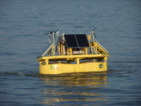 A full-size prototype of the floating lidar offshore resource assessment system, known as FLIDAR, has been successfully tested 15 kilometres off the Belgian coast. It was located next to a stationary lidar (WINDCUBEv2 lidar from Leosphere) on a fixed communication mast for the month of October 2011 in order to test survivability and validate the accuracy of the wind speed measurements.
By Bruce Douglas, Sales & Marketing Director, 3E, Belgium
- Details
- Category: Articles
 Historically, small wind turbine (SWT) manufacturers have not had to undergo the same stringent certification procedures as large wind turbine manufacturers, and SWT test data has often been provided by manufacturers without verification and in varying formats, making it difficult for consumers to compare products. To enable consumers to make an informed decision when purchasing a SWT, a method for consumer labelling has been developed under the wings of the International Energy Agency (IEA) and the International Electrotechnical Commission (IEC). This labelling method can also be of benefit to professional buyers of SWTs and should spur the industry to develop better products. Some manufacturers of SWTs have already done much of the type testing according to IEC standards, which is required for the label, and expect to apply the label to their products during 2012.
By Sven Ruin, TEROC AB, Sweden, and Jonathan Whale, Murdoch University, Australia
- Details
- Category: Articles
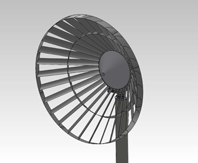 The Ecowhisper Wind Turbine (EWT) is built from a number of interdependent systems. The Blade Array interacts with the wind and its performance determines the overall performance of the whole EWT system. In this article the different interdependent systems are described.
By Stephen Thomas, Chief Technical Officer, RESA, Australia
- Details
- Category: Articles
 In the past five years many aspects of harvesting wind energy from the North Sea have been studied within the framework of the research programme We@Sea. We@Sea was a Dutch government-sponsored programme that ran between 2004 and 2010 and was carried out by a consortium consisting of representatives of all the sectors which are involved in realising large-scale offshore wind energy projects in the North Sea. The sectors included manufacturers of wind turbine systems, research establishments specialised in both technology and marine ecology, electricity companies, technical consultants, NGOs, financial institutions and, last but not least, offshore contractors and operators.
By Jos Beurskens (ECN), The Netherlands
- Details
- Category: Articles
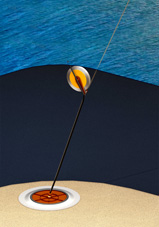 Wind turbines in use today are not able to catch the abundant flow of wind energy a kilometre or so above our heads. This article describes a design for a wind turbine of up to 500MW capacity that could be deployed at many places throughout the world.
By Dr J.M.E. Beaujean, Bogey Venlo BV, The Netherlands
- Details
- Category: Articles
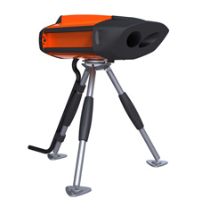 The wind industry is striving to develop new technologies to improve the economic performance and reliability of wind turbines and wind farms. The Lidar (light detection and ranging) technology, mounted on wind turbine nacelles to measure the wind upstream of the turbine, is a promising new tool to reduce uncertainties in annual energy production, reduce O&M costs and optimise power performance.
By Samuel Davoust and Thomas Velociter, Avent Lidar Technology, France
{access view=!registered}Only logged in users can view the full text of the article.{/access}{access view=registered}The Wind Iris is the first of a new generation of nacelle-mounted lidars designed and tested in the field as wind turbine diagnosis tools. These instruments can be moved from turbine to turbine to perform cost-effective power curve measurements, performance monitoring and the adjustment of turbine static parameters.
Wind Measurements in the IndustryWind measurements are crucial throughout the life cycle of a wind farm, whether for resource assessment, power curve measurements or wind turbine control. Cup anemometers, wind vanes and sonic anemometers are commonly used today to measure the local wind.
The IEC 61400-12-1 standard describes the procedure for power performance measurement. According to this standard, the horizontal wind speed should be measured at hub height from two to four rotor diameters away from the rotor plane, using a mast-mounted cup anemometer. However, the installation and dismantling of a met mast can be long, difficult and expensive (up to € 50,000 for an 80-metre tower, excluding equipment cost). This cost increases dramatically for taller masts, in complex sites and offshore. As a result very few power curves can be measured (two to four turbines maximum) when a wind farm is commissioned or during its subsequent operation.
New Perspectives Offered by Lidar Remote Sensing
Introduced several years ago, the portable ground-based Lidar is a remote sensor that is a cost-saving alternative to met mast measurements. This technology is now mature, and the IEC 61400-12-1 standard is currently being revised to include such remote sensing measurement devices.
By measuring entire vertical wind profiles up to 200 metres (a region that is out of reach of mast-mounted cups), these 'towers of light' provide crucial additional information to further reduce uncertainties for resource assessment and power curve measurements. For power performance applications, just as with a mast, ground-based Lidar can cover only a selected wind sector in front of each turbine. By utilising a nacelle-mounted Lidar, however, the measured wind is always aligned in the direction of the turbine: wind is measured as turbines experience it.
Specific Features of Nacelle-Mounted Lidar
Nacelle-mounted lidars should be designed under specific constraints imposed by the turbine operating environment. The Lidar needs to be very robust due to the additional challenges of up-tower operation (vibrations, lightning, electromagnetic fields, etc.). The high cost of interventions on wind turbines demands a high Lidar reliability, and therefore Lidar architectures with no moving parts are preferable. As with any turbine operation, safety should come first, and nacelle-mounted lidars need to be designed so that the mounting and un-mounting can be easily and safely performed.
Wind Iris Turbine Performance Analysis Lidar
Avent Lidar Technology manufactures and sells the Wind Iris, a two-beam Lidar that measures the horizontal wind speed and direction at hub height and at ten distances from 40 to 400 metres upwind of the turbine, simultaneously measured with an acquisition frequency up to 10Hz (see Figures 1 and 2). Designed specifically for turbine operations based on operational experience, this Lidar is robust and easy to deploy. Its first purpose is to reproduce the met mast hub-height measurement, which guarantees that the measurements are useful immediately. However, in addition to this, the flexible pulsed Lidar technology opens up many new possibilities. But first, as with any new measurement instrument, solid field validations need to be obtained.
Field Validations
The reliability and the precision of the instrument have been proven in the field by industry experts. A measurement campaign at the Alpha Ventus wind farm located off the German coast, performed in collaboration with DEWI and Areva Wind GmbH, proved the robustness of the instrument in harsh offshore conditions (ref. 1). A test campaign performed at Risø’s Hovsore test site (ref. 2) has shown that this two-beam nacelle Lidar could measure the horizontal wind speed with a difference of less than 1% compared to an IEC 61400-12 met mast set-up (see Figure 3). Current research focuses on submitting a detailed measurement protocol in order to include nacelle-mounted Lidar power curves in a future revision of the IEC 61400-12 standard.
Reducing Cost, Uncertainty and Duration of a Power Curve Measurement
With installation taking no more than half a day, the cost of measuring power curves using the Wind Iris is drastically less than with a met mast, especially offshore. Figures 4 and 5 show two power curves that have been measured under exactly the same conditions using a IEC set-up mast and the nacelle-mounted Lidar. There is a good agreement between these two power curves and a reduction in the dispersion of data points for the one measured by Lidar. Power curves are thus measured with less uncertainty because of the permanent upwind alignment of measurements. Also, more wind sectors can be considered: regions where the mast was previously in the wake of other turbines or obstacles now provide valid measurements. Power curves can be obtained more quickly.
Extending Power Curve Measurements
Reduction in the cost and duration in power curve measurements leads to improvements in several applications. Firstly, wind turbine prototypes can be tested quickly and in various sites. Secondly, more power curve measurements can be performed during wind farm commissioning, reducing uncertainties further and thereby reducing the cost of wind farm projects. Finally, in operating wind farms the Wind Iris can be moved from turbine to turbine in order to assess and monitor performances, leading to faster decisions for maintenance operations.
Turbine Performance Optimisation
Beyond performance monitoring, nacelle-mounted Lidar are valuable wind turbine optimisation tools. Upwind wind speed and direction measurements can be used to calibrate correction functions for nacelle-based instruments of new turbines, or to adjust those on existing under-performing turbines. For example, permanent yaw errors can be detected and corrected.
Taking a whole wind farm, wind sector management can be optimised by detecting wind speed deficit and turbulence intensity perceived by each turbine as a result of nearby wakes. This leads to new strategies for global power optimisation and exclusion of wind sectors.
Conclusion
Nacelle-mounted Lidar designed specifically for use with wind turbines is a new tool available to the market. Power performance analysis applications, which previously needed a mast, can now be extended to areas that were inaccessible and performed at a reduced cost. New power performance optimisation applications, making a complete use of the instrument output, are also emerging.
At a later stage, retrofitting turbines with Lidar-assisted control using this technology will bring adaptive solutions for under-performing wind farms in difficult sites, until a new generation of wind turbines integrating Lidar as a core component emerges.
Further Reading
- Cañadillas, B. and Neuman, T. First test of a nacelle-based 2-beam wind LiDAR system under offshore conditions. DEWI Magazin no. 39, August 2011.
- Wagner, R. et al. Power performance measured using a nacelle Lidar. EWEC Proceedings 2011.
Samuel Davoust is Scientific Product Manager at Avent Lidar Technology. Prior to joining Avent, Samuel was investigating rotating turbulent flows with laser-based techniques at ONERA, the French Aerospace Lab. He holds a PhD in fluid mechanics from École Polytechnique in Palaiseau and an MSc in aeronautical engineering from ISAE, Toulouse, France.
Thomas Velociter is Directeur Général of Avent Lidar Technology. In 2008, Thomas joined Leosphere, leader in Lidar atmospheric observations, to undertake the development of wind turbine mounted Lidar activity, leading to the creation of Avent. Thomas holds a degree in optical engineering and high-tech business management from Institut d’Optique Graduate School, Palaiseau, France.
Avent Lidar Technology is a joint investment of Leosphere and NRG Systems dedicated to developing, manufacturing and selling nacelle-mounted lidars.{/access}
- Details
- Category: Articles
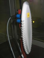 Reliable operation, consistent performance, reduced maintenance and improved safety are key drivers for the wind turbine business. Consequently, Labkotec Oy decided to put its latest generation of ice detector, the LID-3300IP, through a rigorous independent testing regime to ensure that it would meet the standards demanded by modern wind energy operators.
By Jarkko Latonen, Chief Technical Officer, Labkotec Oy, Finland
Windtech International wants to make your visit to our website as pleasant as possible. That is why we place cookies on your computer that remember your preferences. With anonymous information about your site use you also help us to improve the website. Of course we will ask for your permission first. Click Accept to use all functions of the Windtech International website.


